Blender panel lines

Coming from a background of building Gunpla, it was inevitable that at some point I would want to learn how to transfer over various techniques to blender when doing modeling. A lot of the stuff I tend to model is mecha stylized which will always include some kind of panel lining.
here are some examples of panel lines:
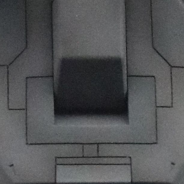
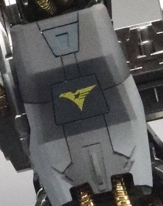
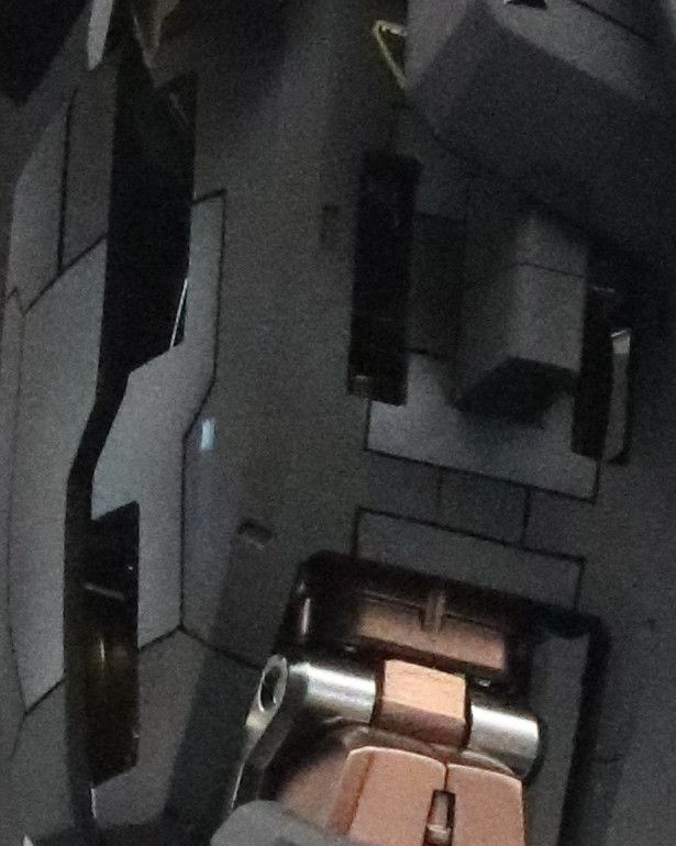
These are some screen grabs of my RX 78-2 Perfect grade where I painstakingly engraved hundreds of custom panel lines using a plastic scriber.
When working with panel lines, especially when mecha is concerned, careful considering must be taken to make sure it ‘looks right’. By this I mean that there is a certain aesthetic that when executed correctly, does a better job of selling that ‘mecha’ style.
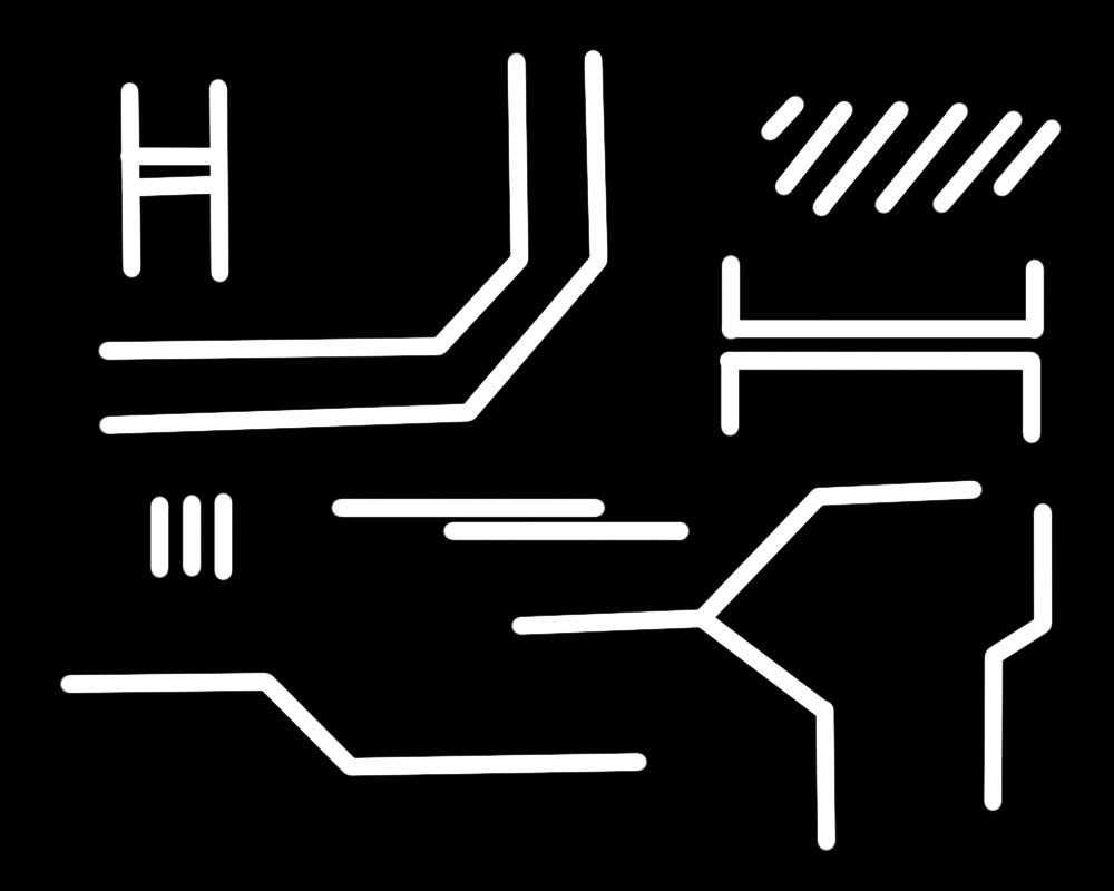
45 Degree angles
Panels on mechas tend to want to mimic the anthropomorphic form and thus are not always simply just square. By contrast, they want to tend towards more oblique shapes, but considering they want to be easy to manufacture, we tend to represent this via 45 deg angles instead of curves (as far as possible). In the above screenshots, the 45 deg angles allow interesting access panels to be created. This is an important characteristic of mecha.
Try keeps lines parallel
once you introduce 45 deg angles, you should try and use them to connect lines which are parallel. Parallel lines not only look good, but help to enforce the idea that there are pseudo ‘panels’ which can be removed. The more parallel lines there are, the more machine-like it tends to look. It also sells the idea that it was designed like this on purpose, keeping in mind we want to ground these machine in a future that makes sense, as if manufacturing techniques evolved in a way that is believable.
Symmetry
In the above examples, there are very clear planes where you can see a virtual line could be drawn allowing the design to be reflected. In the case of a mecha, this is usually the vertical axis to mirror the body, but often also on individual pieces such as the leg parts shown above. Symmetry also helps ground a design more in reality because it again sells the idea that manufacturing the concept is easy. The more parts which use the same patterns, the easier to manufacture and the easier to mass-produce.
Use angles to create islands
Not all panels need to meet up in a repeating array based pattern with simple corner to corner connections. That is to say, that some panels next to each other (while maintaining the above traits) can be represented as more complex polygons. Angles are a great way to create ‘islands’ that break up the design with interesting focus points
try to maintain a constant volume with each panel
When creating lines to separate panels, make sure that each panel which fits into a specific size-grade (large / small / tiny) maintains the same sort of volume. This make accessing the mechanics behind the armor easier for technicians, but also helps with uniformity.
step 1: modeling
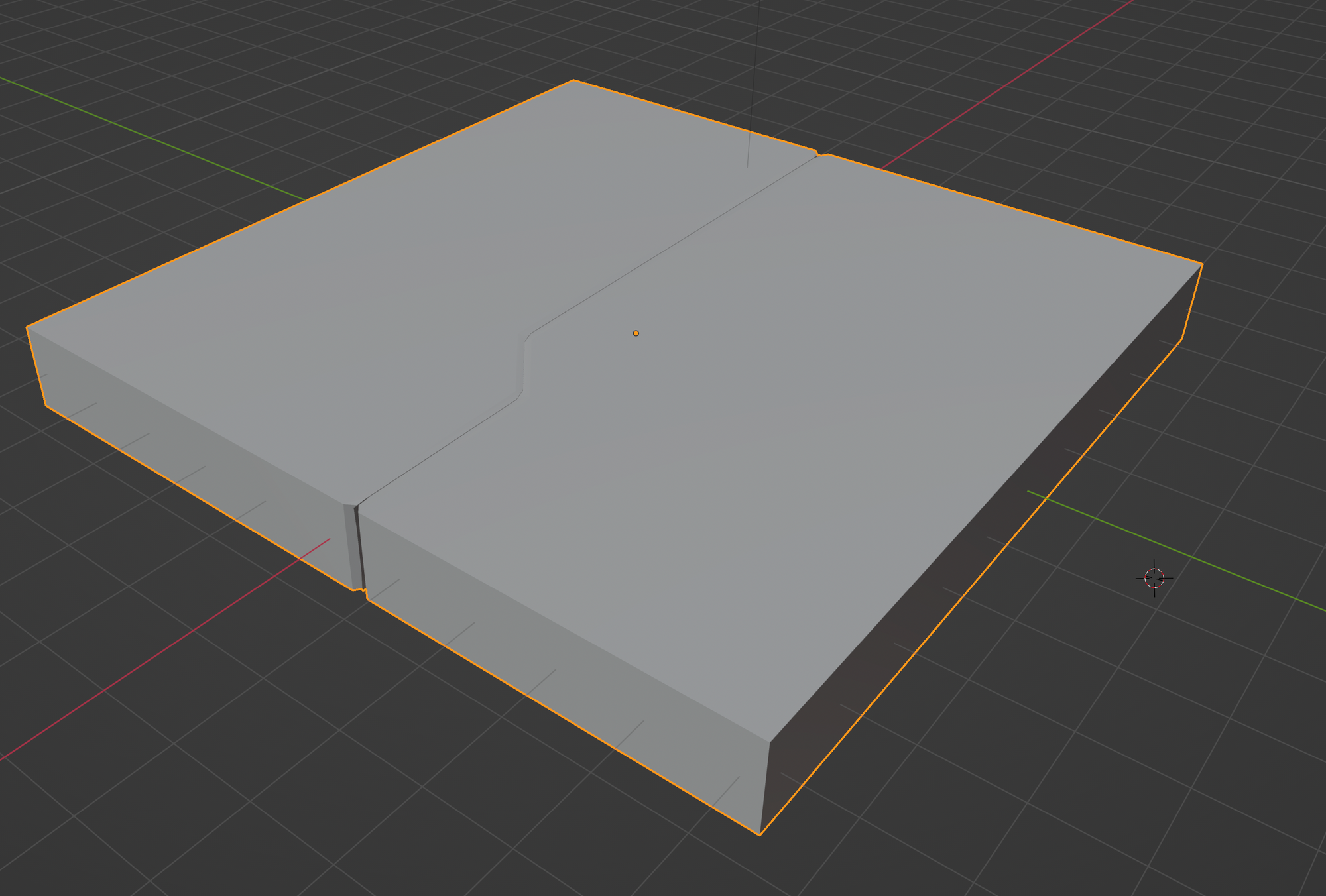
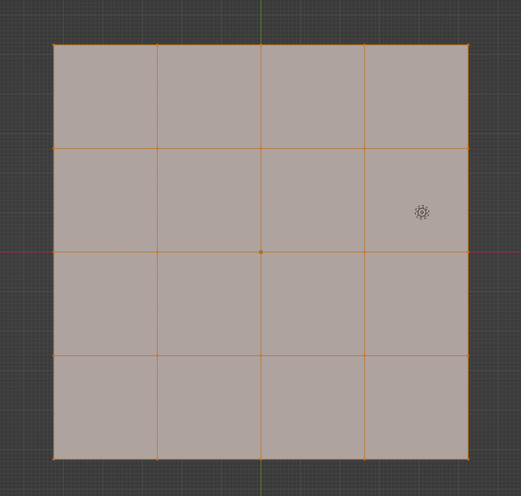
First we start with a cube (but this can be any form) and we subdivide it a few times so we can get more vertices to work with. You can also use the loop cut tool to create panels without unnecessary vertices (I just used subdivide since it was the quick and easiest method in this example).
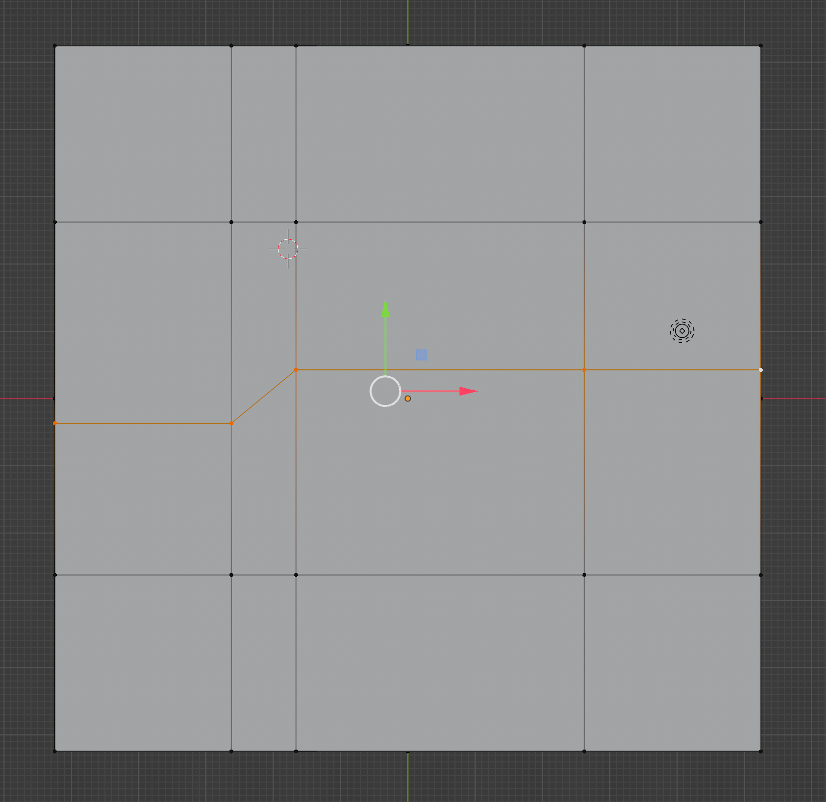
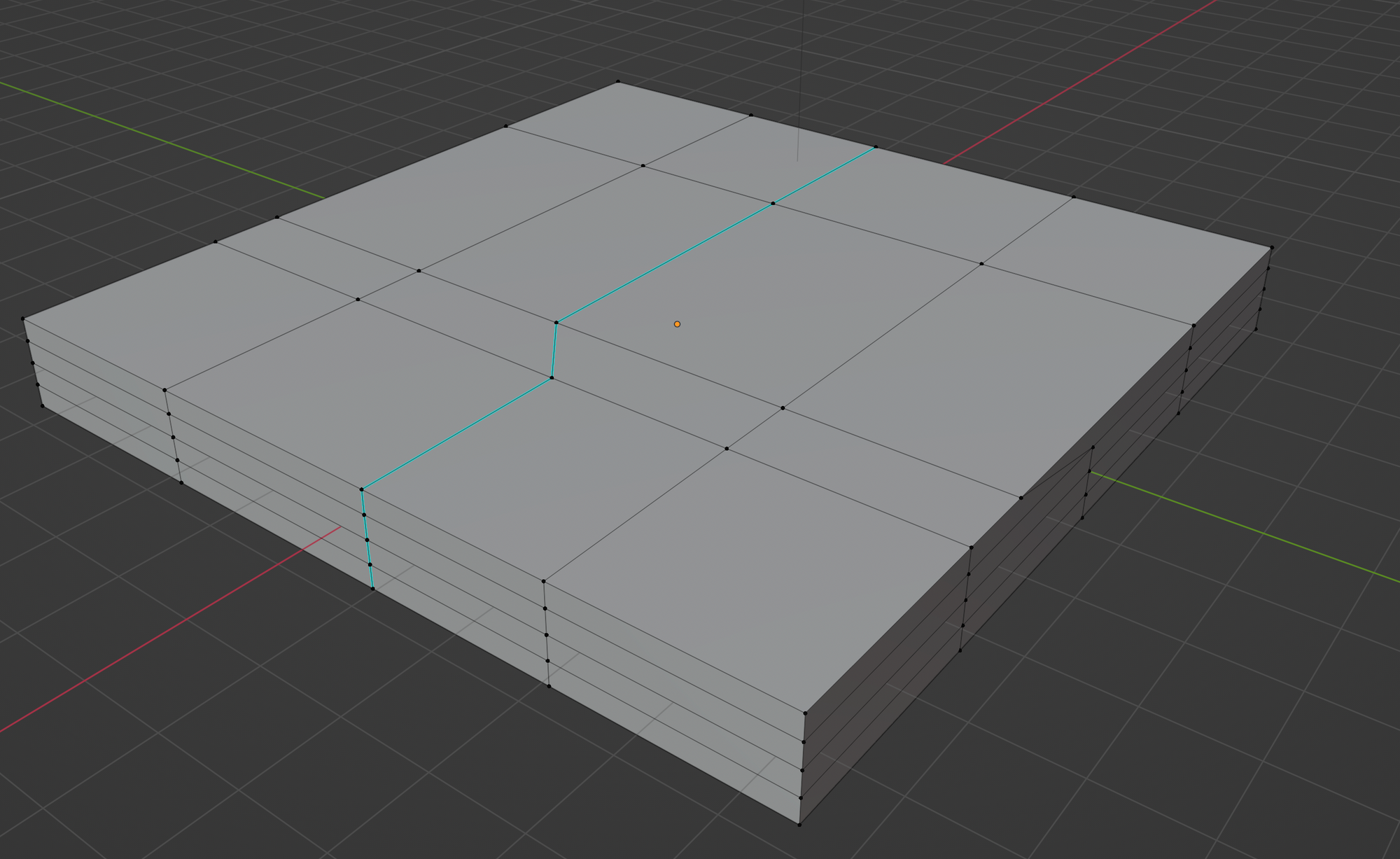
Next we use the move tool to shift various vertices around while constrained to a specific axis to create a 45 deg angle with two parallel lines.
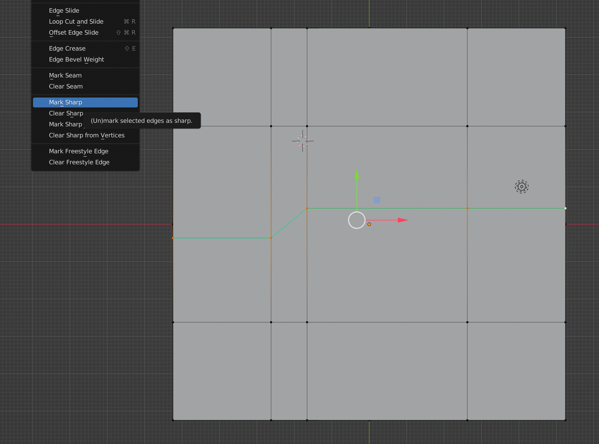
Then we mark these edges as sharp. You will notice that when in edit mode, they get a blue line indicating this.
Since we want panel lines to run around all sides of the form, I do this for all planes:
The last thing we want to do while in edit mode, is assign these vertices which represent the sharp edges into a new vertex group (we can call it ‘panel line’).
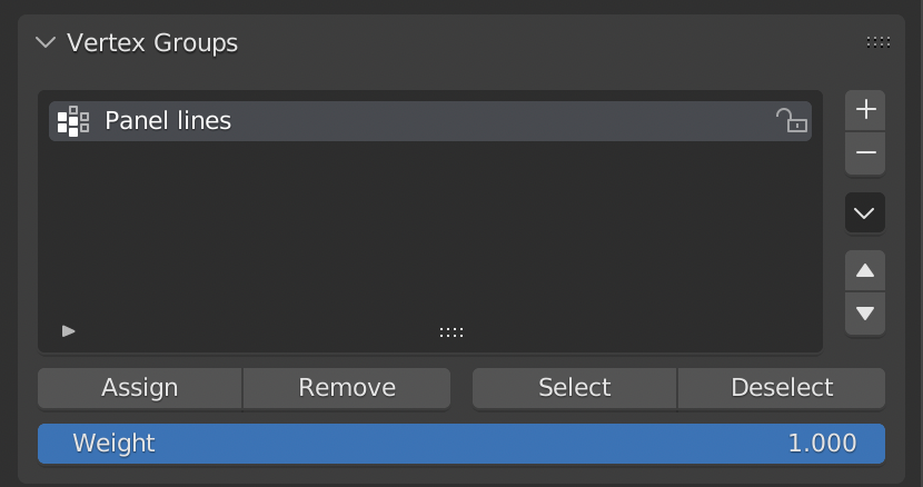
At this point we have sliced up our geometry without actually slicing up the geometry itself. We can not use a set of modifiers in object mode to turn these selected edges into panel lines!
Step 2: use modifiers
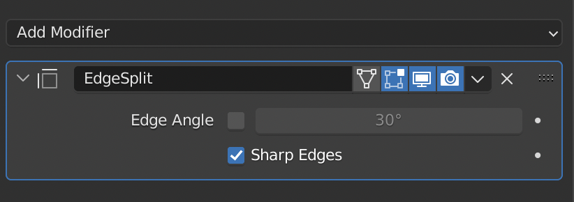
Now we can split up our geometry using the edges we marked as sharp. Add an edge split modifier:
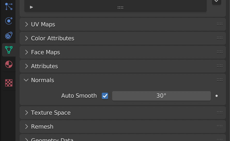
Now we turn on auto-smoothing under the ‘normals’ section of the geometry.
Now that we have split our geometry, we can virtually join it again into a single form:
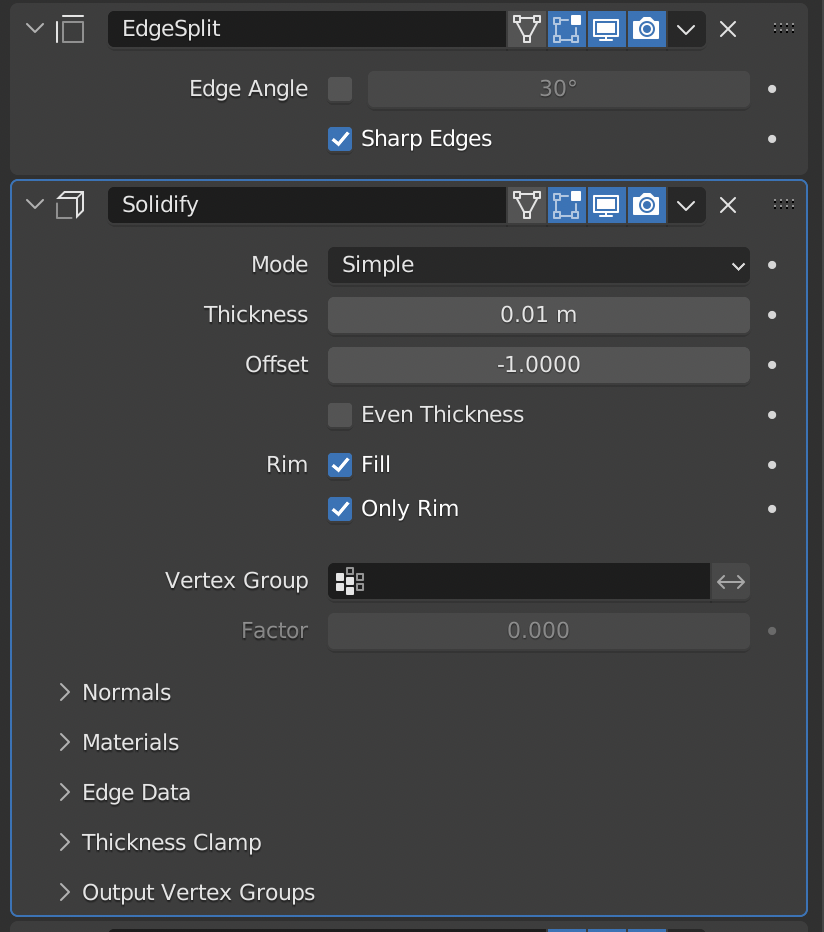
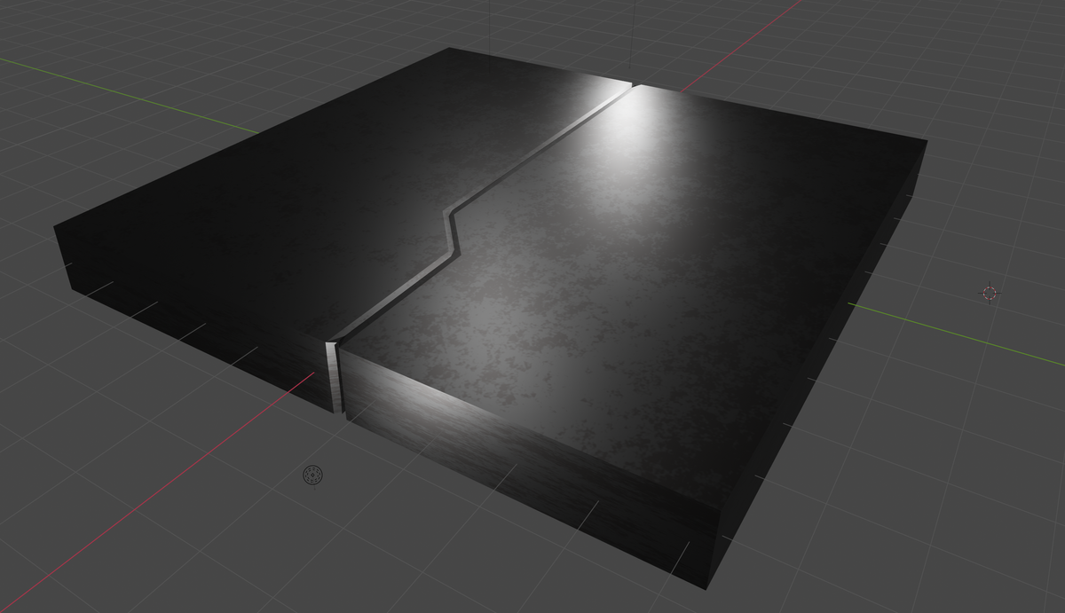
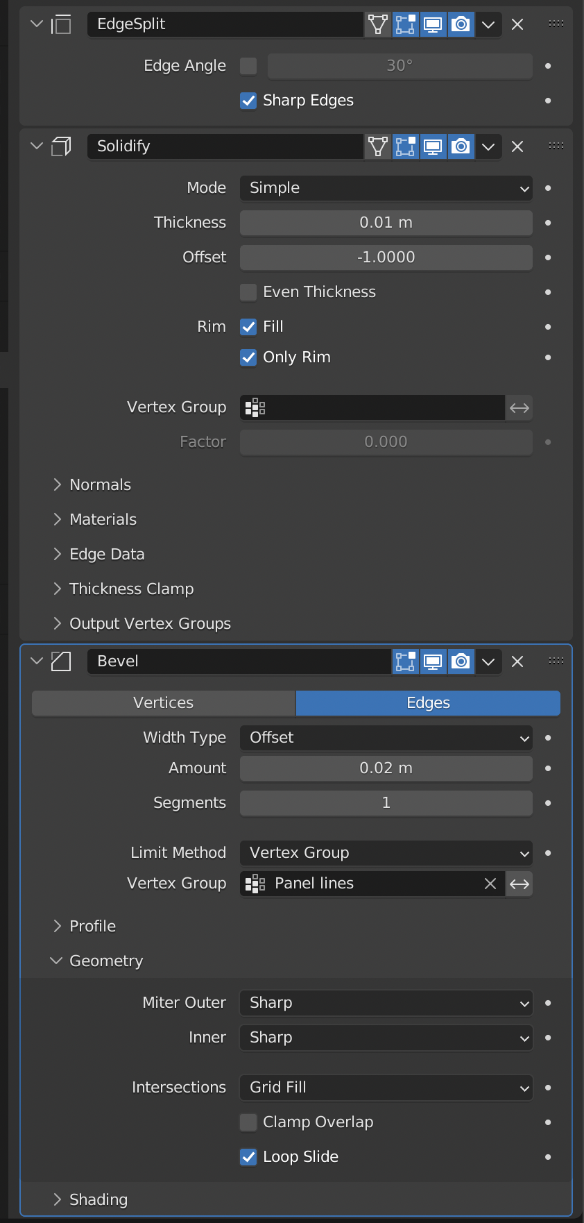
While this seems counter-intuitive, we have now generated a model that has virtual ‘edges’ which when given a bevel modifier, will add a 45 deg angle to each edge effectively creating a ‘seam’ which represents our panel lines.
When adding the bevel modifier, make sure to deselect the ‘clamp overlap’ and set the Limit method to our vertex group we created while in edit mode. This ensures that the bevel only applies to the edges we want and not the entire form.
And here we have the final panel lines!